
Magnetic Coupling Containment Shell Selection: Eddy Current Loss, Pressure Ratings, and Material Trade-offs
Magnetic coupling containment shell selection: compare eddy current losses, pressure design and material trade-offs. Use the checklist to prepare your OEM RFQ.
Magnetic coupling containment shell selection starts with three linked checks: chemical compatibility, pressure integrity at temperature, and the heat generated inside the magnetic gap. A material that reduces electrical losses can still fail the pressure, creep, clearance, or torque requirements. Select the complete shell-and-rotor design rather than buying an alloy name or a nominal pressure rating.
Reviewed: November 5, 2026. Scope: preliminary selection and RFQ preparation for global pump OEMs, rotating-equipment engineers, and industrial buyers considering synchronous coaxial permanent magnet couplings. The calculations below are illustrative screening examples, not measured MagAtom product results or certified pressure designs. Applicable codes, contract editions, chemical compatibility, and acceptance limits must be established for the actual installation.
Permanent magnet couplings transmit torque across a stationary barrier without a rotating shaft penetration through that barrier. This removes a dynamic shaft seal from the coupling boundary, but static joints, corrosion, rotor contact, and pressure excursions still require engineering controls. The containment shell, also called an isolation can or containment shroud, separates the process liquid from the outer driver rotor.
For a first review, send your drawing, fluid composition, pressure, temperature, torque, and speed range through the MagAtom engineering contact form. The checklist below explains which evidence to request before approving a replacement or a new assembly.
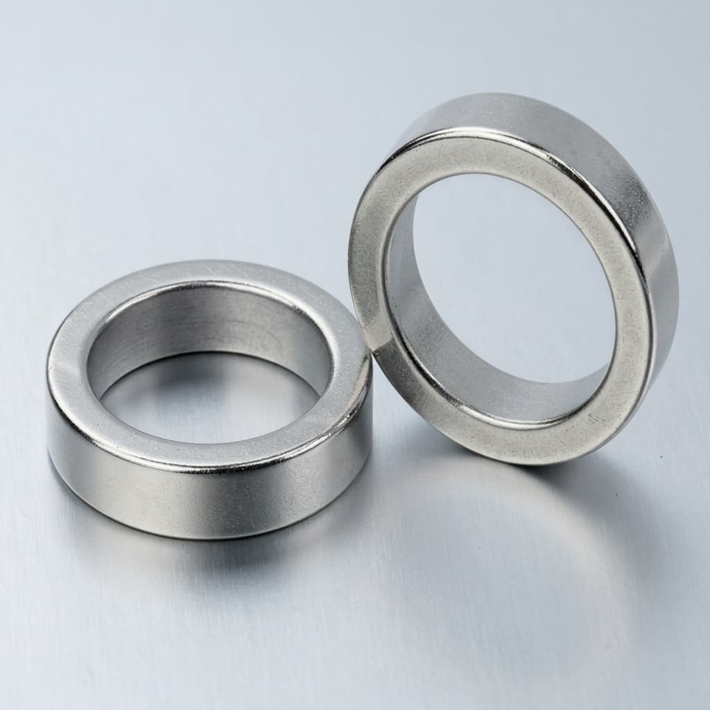
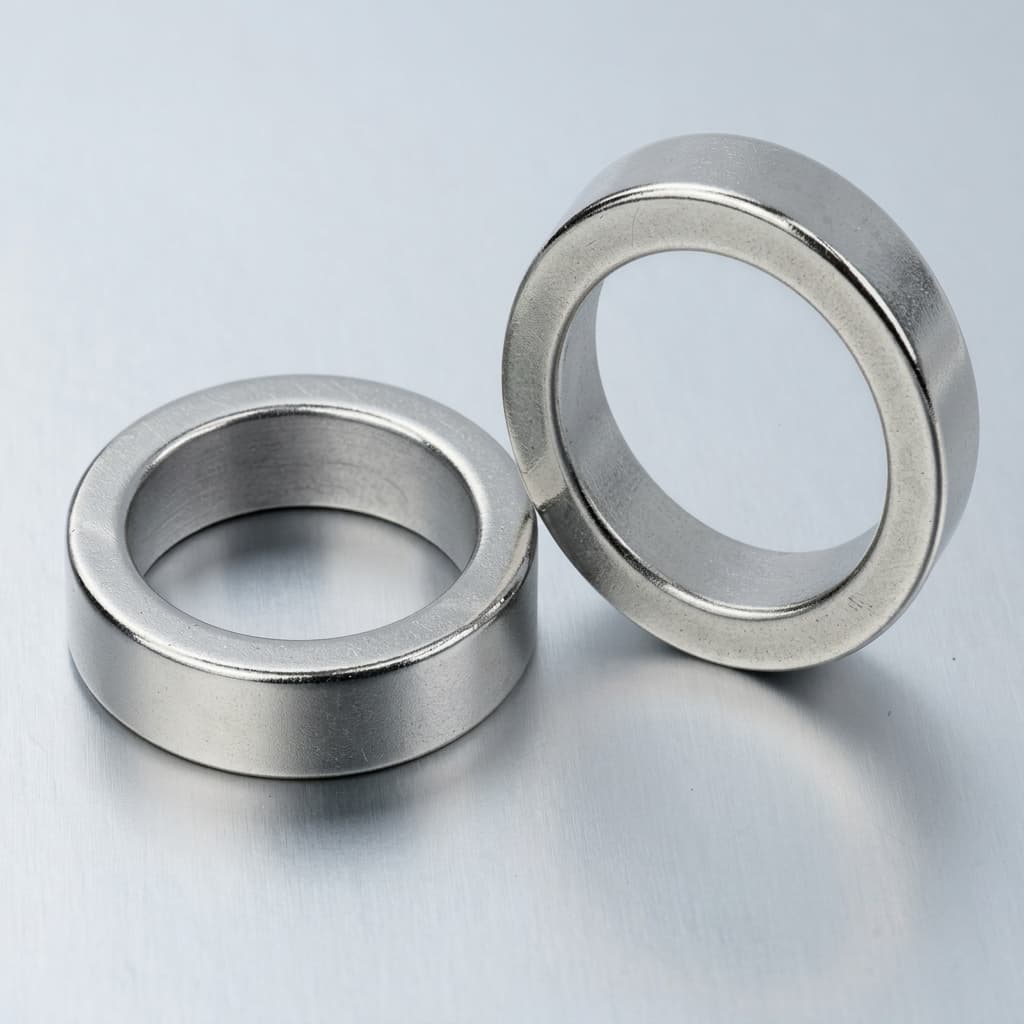
Illustrative ring components. The schematic in Section 2 explains the complete containment architecture; the photograph does not establish a shell material or pressure rating.
1. Operating architecture and eddy current loss
A synchronous coaxial permanent magnet coupling comprises three concentric zones:
- Outer magnet rotor: connected to the motor or gearbox and carrying alternating magnetic poles.
- Stationary containment shell: attached to the equipment casing and forming part of the process pressure boundary, including its closed end, flange, and seals.
- Inner magnet rotor: connected to the driven shaft and exposed to the process environment through the assembly's specified encapsulation and circulation arrangement.
Although the two rotors normally turn synchronously, their field moves relative to the stationary shell. An electrically conductive shell therefore experiences induced currents and resistive heating. Synchronous operation does not eliminate this loss.
Use relative loss estimates within their limits
For the same geometry and magnetic field, a simplified thin-wall, low-skin-effect comparison gives eddy current loss proportional to B² × n² × t / ρ, where B is the field amplitude at the shell, n is speed, t is wall thickness, and ρ is electrical resistivity. This is a trend model, not an absolute wattage equation. Pole count, end effects, harmonics, temperature, field reaction, and current paths affect the actual loss.
For an unchanged coupling under these assumptions, raising speed from 1,500 to 3,000 rpm gives a loss multiplier of (3000 / 1500)² = 4. That estimate is useful when flagging a proposed VFD speed increase, but it cannot establish the required cooling flow. Obtain a supplier loss map or validated electromagnetic model across the operating range.
Reducing thickness can reduce electrical losses while weakening the shell. Increasing electrical resistivity can reduce induced currents, but changing material also changes strength, corrosion behavior, thermal expansion, and the achievable wall geometry. A relative loss number is meaningful only when those assumptions are stated.
2. Containment shell architecture: cross-sectional diagram
The schematic shows the driver, stationary pressure boundary, follower, and internal circulation passage. It is conceptual and not to scale. Clearances and wall thickness are design outputs, not installation dimensions taken from the drawing. Flux crosses the shell; induced currents circulate within a conductive shell.
Figure 1: Cross-Sectional Magnetic Flux and Eddy Current Induction Model
3. Pressure ratings and wall thickness: screening versus approval
A containment shell does not have a universal pressure rating based on material alone. Diameter, minimum finished wall, unsupported length, end geometry, welds, flange attachment, temperature, degradation allowance, and manufacturing tolerances all affect the complete pressure boundary.
Start by defining the maximum internal and external differential pressures. Include shutoff and transient conditions, suction vacuum, shutdown, and any pressure in a secondary housing. State absolute or gauge pressure explicitly. Internal-pressure resistance and external-pressure buckling are separate checks; passing one does not establish the other.
A reproducible internal-pressure screening example
For an ideal thin cylindrical wall, hoop stress can be screened with σ ≈ P × r / t, or t ≈ P × r / S, where P is differential pressure, r is radius, t is wall thickness, and S is an assumed allowable stress. Use consistent units: MPa equals N/mm².
Illustrative inputs: P = 2 MPa, r = 50 mm, and assumed S = 100 MPa. The membrane estimate is t = 2 × 50 / 100 = 1.0 mm. The assumed stress is not a published allowable for any material in this article. The result excludes joint factors, forming tolerances, corrosion allowance, local stresses, fatigue, the closed end, flange, and external buckling. It is a feasibility calculation, not an approved drawing thickness.
If the project specifies ASME BPVC Section VIII, the responsible designer must use the applicable rules, material/product-form allowables, temperature, and examination requirements. A coupling component is not automatically a code-stamped pressure vessel because a familiar shell equation was used. Local pressure-equipment obligations depend on the installation and jurisdiction.
External pressure and polymer creep need separate evidence
Thin shells can be sensitive to ovality, unsupported length, end restraint, and manufacturing imperfections under external pressure. Request a code-based external-pressure assessment or validated structural analysis rather than a generic collapse equation. For polymers and composites, include time-dependent creep, fiber direction, fluid exposure, and pressure cycling. A short ambient hydrotest cannot establish long-term hot-service capability.
4. Material comparison matrix for supplier discussions
This matrix compares selection questions, not interchangeable pressure ratings. Every candidate needs a pressure-temperature envelope for its finished geometry. No maximum temperature, pressure, or wall thickness can be assigned from the material family alone.
| Material candidate | Electrical-loss consideration | Structural and process trade-off | Evidence needed before selection |
|---|---|---|---|
| Hastelloy C-276, UNS N10276 | Conductive; shell heating remains | Candidate for corrosive service; compatibility depends on composition and temperature | Alloy certificate, finished minimum wall, corrosion assessment, loss map |
| 316L stainless steel, UNS S31603 | Conductive; calculate losses for the proposed wall | Consider where process compatibility and fabrication are acceptable; assess localized corrosion | Chemistry review, weld condition, temperature-specific design calculation |
| Titanium Grade 5, Ti-6Al-4V | Evaluate the exact grade and geometry; no universal percentage saving | Strength and fabrication route may permit a different wall; chemical approval is essential | Product-form data, compatibility statement, weld qualification, loss calculation |
| Titanium Grade 2, commercially pure | Do not substitute Grade 5 electrical data | Different strength and chemistry from Grade 5; not an equivalent shell by name | Exact grade certification and a separate structural and thermal assessment |
| Carbon-fiber-reinforced PEEK | Carbon reinforcement can conduct; do not assume zero loss | Stiffness, anisotropy, creep, molding quality, and chemical exposure affect behavior | Exact compound, directional properties, hot creep data, finished-shell heat test |
| Unfilled PEEK | Insulating polymer can substantially reduce shell eddy currents | Stiffness and long-term creep may require a larger magnetic separation | Fluid-conditioned creep data, pressure-cycle qualification, hot torque curve |
| Yttria-stabilized zirconia ceramic | Insulating ceramic can substantially reduce shell eddy currents | Brittle behavior, defects, mounting loads, and thermal gradients govern reliability | Qualified ceramic specification, assembly load analysis, thermal-cycle and proof-test plan |
A zero or very small shell eddy-current contribution does not mean zero assembly heat. Bearing friction, liquid circulation, rotor losses, and transmitted-load losses still need to be included. Compare total system behavior at the same duty point.
5. Detailed material trade-offs and decision boundaries
Hastelloy C-276: use temperature-specific data
Haynes reports C-276 electrical resistivity of 1.23 µΩ·m at room temperature, equivalent to 123 µΩ·cm, in its physical-properties table on PDF page 13. Its corrosion charts distinguish acid concentration and temperature; they do not establish compatibility with every process mixture. Use the Haynes C-276 datasheet for those inputs, then review contaminants, weld condition, and service exposure separately.
For selection, ask whether the approved shell thickness and resulting loss can be accommodated by the available internal circulation. A corrosion-resistant metal remains a conductive barrier. If heat rejection is the limiting constraint, compare another qualified design at the same pressure and torque requirements rather than assuming one alloy substitution solves the problem.
Titanium: compare the specified grade and manufacturing route
Treat Grade 2 and Grade 5 as different candidates. A strength advantage matters only if the finished-shell design can use it without losing buckling resistance, tolerances, weld integrity, or corrosion compatibility. Require a grade-specific assessment for the actual fluid and cleaning chemistry, including hazardous or reactive media. An alloy's strength does not establish its suitability for that chemical service.
Also compare minimum-wall inspection access, fabrication cost, repair policy, and the loss calculation. A thinner nominal wall is not a saving if forming variation or inspection limits make the required minimum unreliable. Keep the drawing revision and material/product specification attached to each quote.
CFR-PEEK: distinguish reinforcement from electrical insulation
Carbon-filled PEEK must not be described as a perfect insulator. The Victrex 450CA30 datasheet, March 2026 revision reports volume resistivity of 1.0 × 10⁵ Ω·cm at 23°C, measured at 1 V. It also reports tensile stress at break of 265 MPa at 23°C and 85 MPa at 175°C. These are material-comparison data, not allowable design stresses or a pressure rating for a molded shell.
For a supplier comparison, identify the exact compound and reinforcement arrangement. Request conductivity assumptions and validation of the complete shell, including conductive inserts. Evaluate creep over the intended operating life. Lower electromagnetic heating does not remove the need for bearing lubrication or process circulation.
Unfilled PEEK and zirconia: inspect the complete assembly
An insulating pressure boundary can reduce the heat source associated with a metallic can. The benefit must be assessed alongside wall thickness, running clearance, and torque at temperature. Polymer creep and chemical aging require different qualification evidence from ceramic fracture and thermal-gradient sensitivity.
For ceramic candidates, ask how mounting preload, edge contact, handling damage, and rapid temperature changes are controlled. For polymer candidates, ask how time, pressure, temperature, and absorbed process fluid affect dimensional stability. Neither a ceramic compressive-strength number nor a polymer short-term tensile test establishes shell working pressure.
6. Thermal failure dynamics and cooling requirements
One plausible failure sequence is shown below. It describes a mechanism to evaluate, not a measured frequency ranking or a universal temperature threshold.
Conductive shell generates heat
             ↓
Local circulation cannot remove the combined heat load
             ↓
Fluid approaches its bubble point at local pressure
             ↓
Vapor formation can impair bearing lubrication and cooling
             ↓
Bearing damage, rotor contact, or magnet overheating may follow
             ↓
Containment integrity can be lost
Turn the mechanism into design checks
- Establish the local heat balance. Include shell loss, bearing and fluid-friction heat, operating speed, inlet temperature, and the actual internal circulation rate. Process discharge flow is not automatically the flow through the rotor annulus.
- Check local pressure and vapor margin. Compare predicted fluid temperature with the mixture's bubble point at the lowest relevant local pressure. Specify an agreed margin for normal operation, startup, and credible upset conditions; a fixed temperature rise cannot guarantee protection for every liquid.
- Define monitoring and response. Agree sensor location, temperature or power monitoring, alarm and trip thresholds, and shutdown behavior with the pump OEM. If rub protection or secondary containment is required, document its function and qualification.
Do not specify a sealless pump's internal circulation solely by mechanical-seal flush-plan numbers. Require an OEM circuit drawing showing passages, restrictions, pressure drops, bearing flow, and heat removal. Instrumentation and acceptance requirements must be tied to the applicable contract and standard edition, rather than presented as universal API mandates.
7. SmCo versus NdFeB under thermal stress
Containment material and magnet grade must be reviewed together, but a metallic shell does not automatically require SmCo, and an insulating shell does not automatically qualify NdFeB. Select from the actual magnet temperature, hot torque requirement, and demagnetization behavior of the assembly.
Permanent magnets can show reversible changes in flux as temperature changes. Irreversible demagnetization depends on the grade's temperature-dependent demagnetization curve and the operating magnetic circuit. Curie temperature is not a permissible continuous operating temperature. Rotor encapsulation, adhesives, coatings, and retention components may impose a lower assembly limit.
Request the grade-specific demagnetization curves and a torque-versus-temperature assessment at the proposed magnetic separation. Confirm transient and stalled or decoupled conditions as well as steady operation. SmCo can be a candidate when temperature stability is important; the supplier must still substantiate the selected grade and operating point. Neither material family guarantees that rated torque is retained at an arbitrary hot-shell temperature.
8. Failure modes and mitigation questions
Use these six failure modes to structure the design review. The actions are engineering questions, not standardized clearances or automatic material replacements.
| Failure mode | Conditions to examine | Detection or evidence | Review action |
|---|---|---|---|
| Rotor-to-shell contact | Runout, bearing wear, alignment, thermal growth | Clearance stack, vibration trends, contact inspection | Verify cold and hot clearances and the OEM's contact-protection strategy |
| Local flashing | Low local pressure, hot liquid, restricted circulation | Local heat balance, pressure map, temperature trends | Confirm circulation and vapor margin across the speed range |
| Corrosion or cracking | Actual mixture, contaminants, stress, weld condition | Compatibility review, inspection history, material traceability | Reassess material and inspection interval for the specific service |
| External collapse | Vacuum, secondary-housing pressure, ovality | External-pressure calculation, tolerances, defined proof procedure | Qualify the shell for the maximum external differential pressure |
| Thermal-cycle damage | Startup, cleaning, rapid temperature gradients | Assembly thermal-cycle qualification and crack inspection | Specify allowable ramp rates and mounting conditions |
| Particulate wear | Solids entering narrow circulation or bearing passages | Fluid cleanliness specification and passage inspection | Evaluate compatible filtration or separation with its pressure-drop effect |
A mitigation can introduce another constraint. For example, filtration can restrict circulation as it loads, while additional wall thickness can increase loss or widen magnetic separation. Require the supplier to show the updated pressure, heat, and torque balance after a design change.
9. Procurement and engineering RFQ checklist
Give competing suppliers the same duty envelope and drawing revision. A useful quotation states assumptions, exclusions, evidence deliverables, and acceptance conditions; it does not replace them with a generic claim of standards compliance.
Hydraulic and mechanical boundaries
- Maximum internal and external differential pressure, including shutoff, transients, vacuum, and secondary-housing conditions; identify gauge versus absolute units.
- Continuous, startup, cleaning, and upset temperatures, including ramp rates and required operating life.
- Minimum, rated, and maximum speed; acceleration, deceleration, and permitted duration of off-design operation.
- Continuous and transient torque, required hot pull-out margin, driven inertia, and response to decoupling.
- Interface drawing revision, minimum finished wall, full magnetic separation, runout, and cold/hot clearance stack.
Fluid and thermal management
- Full process composition, concentrations, contaminants, solids, and cleaning chemicals.
- Density, heat capacity, viscosity, and vapor or bubble-point information across the operating range.
- OEM internal-circulation drawing, predicted flow and pressure drops, heat sources, and allowable local temperature.
- Loss map at agreed speeds and temperatures, identifying calculated versus measured results and uncertainty.
- Monitoring, alarm and trip logic, and operating restrictions during startup or loss of circulation.
Manufacturing, qualification, and acceptance
- Applicable pressure-equipment requirements, contractual standard editions, and a clause-by-clause compliance or deviation list where requested.
- Exact material grade, product form or compound, traceability, fabrication route, and required certificates.
- Design-specific joint assessment, inspection coverage, minimum-wall measurement, and acceptance criteria.
- Agreed proof-test pressure, medium, temperature, hold duration, and acceptance procedure derived from the applicable requirements.
- Leak-test method, units, sensitivity, and acceptance limit where required; distinguish leak testing from structural qualification.
- Rotor balance criteria, hot torque verification, and heat-run conditions appropriate to the application.
Before ordering, send the completed duty envelope to MagAtom and request confirmation of the available documentation and proposed validation scope. Obtain written agreement on any special tests, third-party witnessing, and secondary containment before purchase.
10. Frequently asked questions
Why can torque change when switching from a metallic can to PEEK or ceramic?
If the replacement needs a thicker wall or different running clearances, it changes the magnetic separation and potentially the available torque. The result depends on the complete magnetic circuit, not a universal inverse-gap equation. A redesigned rotor may recover capacity, but substitution alone does not prove it. Request hot and cold torque curves for the proposed assembly.
Does a dual-wall can automatically provide secondary containment?
No. An additional layer may have a thermal, structural, or monitoring function without being qualified to contain a primary-shell leak. Ask which component forms the secondary pressure boundary, its rated pressure and duration, the detection method, and the shutdown response. A supplier must define the distinction between collecting leakage and retaining pressure after a primary failure.
How can we estimate the circulation needed to remove shell heat?
For a steady-state, single-phase screening balance, use mass flow = heat load / (specific heat × allowable temperature rise). The inputs must describe the local circuit, and the heat load should include other losses that enter it.
Hypothetical shell-only example: assume 3,200 W of shell loss, liquid heat capacity of 2,100 J/(kg·K), and an allowable rise of 8 K. The result is 3200 / (2100 × 8) = 0.1905 kg/s, or 11.43 kg/min. These are assumed inputs, not measured product performance or a recommended operating limit.
If bearing and fluid-friction losses add an assumed 800 W to the same circuit, the estimate becomes 4000 / (2100 × 8) = 0.2381 kg/s, or 14.29 kg/min. This comparison shows why a shell-only calculation can understate circulation demand. Convert to volumetric flow using density at the relevant conditions, then check actual passage resistance, local pressure, heat transfer, and vapor margin. The energy balance alone does not predict where boiling will begin.
Can a metallic shell be slotted to interrupt eddy currents?
Do not cut through an existing pressure shell as a field modification. Slots change the pressure boundary, current paths, and mechanical strength. Any segmented or hybrid concept requires a complete supplier design with pressure, leakage, thermal, and durability qualification. No generic loss-reduction percentage establishes that a modified shell is fit for service.
What establishes chemical compatibility for titanium or PEEK?
Use data for the exact grade or compound, actual fluid concentrations, contaminants, cleaning agents, temperature, and exposure duration. Ask the material producer and equipment supplier to address reactive or hazardous media explicitly. An alloy family name or the phrase “chemically resistant” cannot approve a mixture, and a rejected candidate does not make another material automatically acceptable.
Which MagAtom test results should a buyer request?
Request the proposed inspection and test plan with the quotation. Ask which electromagnetic calculations, hot torque tests, heat runs, proof tests, and leak tests are available for the specific design, how they are performed, and which reports are included. This article does not establish that every MagAtom assembly receives an identical test program or achieves a particular leak rate. Agreed acceptance evidence belongs in the order documentation.
11. Engineering support and custom sourcing
A useful first inquiry combines the pressure and thermal envelope with the interface drawing, required torque, quantity, destination, and document requirements. Mark unknown inputs explicitly so the supplier can separate a feasibility discussion from an approved production specification.
Use the MagAtom contact portal or email [email protected] to discuss the proposed coupling and documentation package. Ask for confirmation of material availability, engineering scope, test capability, lead time, and commercial terms for your project. For other published application guidance, visit the MagAtom engineering blog.
12. Sources and reference boundaries
Sources checked November 5, 2026. These official resources support the specific facts identified below. Material datasheets describe comparison specimens; they do not certify a finished shell. Public standards listings identify documents and do not replace the licensed requirements or establish product compliance.
- Haynes International — HASTELLOY C-276 alloy datasheet. Physical Properties, PDF page 13, supports the temperature-specific resistivity cited in Section 5; the corrosion charts show why concentration and temperature matter. Read the C-276 datasheet.
- Victrex — PEEK 450CA30 technical datasheet, revision March 2026. PDF pages 1–2 provide temperature-dependent specimen strength and finite volume resistivity; page 3 identifies test conditions and application limitations. Read the 450CA30 datasheet.
- American Petroleum Institute — Digital Catalog. Identifies the API 685 sealless centrifugal pump standard family. Use the contractually agreed publication, edition, and applicable requirements for a compliance review. This listing does not substantiate universal clearances, flush-plan numbers, or test thresholds. Consult the API standards catalog.
Author

Categories
More Posts
High-Speed PM Rotor Retaining Sleeve Selection: Interference Fit, Eddy Current Loss, and Material Trade-offs
High-speed PM rotor retaining sleeve selection: compare interference fit, eddy current loss and material trade-offs. Use the checklist to prepare your OEM RFQ.
SmCo vs. High-Temperature NdFeB Selection: Thermal Demagnetization, Knee Points, and Motor Magnet Sourcing
Compare SmCo vs. high-temperature NdFeB motor magnets. Check thermal knee points, GBD limits, and sourcing criteria before sending an engineering RFQ to MagAtom.